try

Sunday, October 31, 2010

Variable Valve Timing

There are a couple of novel ways by which carmakers vary the valve timing. One­ system used on some Honda engines is called VTEC.


ferrari variable cam system
The variable cam system used on some Ferraris
 
VTEC (Variable Valve Timing and Lift Electronic Control) is an electronic and mechanical system in some Honda engines that allows the engine to have multiple camshafts. VTEC engines have an extra intake cam with its own rocker, which follows this cam. The profile on this cam keeps the intake valve open longer than the other cam profile. At low engine speeds, this rocker is not connected to any valves. At high engine speeds, a piston locks the extra rocker to the two rockers that control the two intake valves.
Some cars use a device that can advance the valve timing. This does not keep the valves open longer; instead, it opens them later and closes them later. This is done by rotating the camshaft ahead a few degrees. If the intake valves normally open at 10 degrees before top dead center (TDC) and close at 190 degrees after TDC, the total duration is 200 degrees. The opening and closing times can be shifted using a mechanism that rotates the cam ahead a little as it spins. So the valve might open at 10 degrees after TDC and close at 210 degrees after TDC. Closing the valve 20 degrees later is good, but it would be better to be able to increase the duration that the intake valve is open.

Ferrari has a really neat way of doing this. The camshafts on some Ferrari engines are cut with a three-dimensional profile that varies along the length of the cam lobe. At one end of the cam lobe is the least aggressive cam profile, and at the other end is the most aggressive. The shape of the cam smoothly blends these two profiles together. A mechanism can slide the whole camshaft laterally so that the valve engages different parts of the cam. The shaft still spins just like a regular camshaft -- but by gradually sliding the camshaft laterally as the engine speed and load increase, the valve timing can be optimized.
Several engine manufacturers are experimenting with systems that would allow infinite variability in valve timing. For example, imagine that each valve had a solenoid on it that could open and close the valve using computer control rather than relying on a camshaft. With this type of system, you would get maximum engine performance at every RPM. Something to look forward to in the future...
For more information on camshafts, valve timing and related topics, check out the links on the next page

Variable Valve Timing


With all the scientific technology computing power out there in the world today I have yet to hear an answer to the age old question: What came first, the chicken or the egg? Well the automotive industry has a similar dilemma that continues to plague its existence. Which is more desirable, large displacement and horsepower or smaller displacement and better fuel mileage?
What if you could have a large displacement, high-horsepower engine that you could call upon when you needed it and have a smaller displacement better fuel mileage engine available when you don’t.  For those of you old enough to remember, that would be a “Doublemint” commercial: double your pleasure and double your fun!
Well, that technology is here right now and growing in popularity and it has more names and acronyms than “Carter has pills” (another commercial, for those old enough).
The one that is probably best known is “Displacement on Demand” (DOD), but there is also “Active Fuel Management” (AFM) that GM has laid ownership to; “Multiple Displacement System” (MDS) from Chrysler; “Active Cylinder Control” (ACC) at Mercedes Benz; and “Variable Cylinder Control” (VCM) from Honda.
You may also hear it called cylinder deactivation. But no matter what you call it, the bottom line is that you have the ability to go down the road driving your gas guzzling road thumping V8 (or bigger) and have half or more of your cylinders go dead, start sipping fuel, run more efficiently and gain an increase of fuel economy up to as much as 20 percent. Imagine being on the highway with the cruise on and only 4 cylinders pushing you down the road (because you only need 30 percent of your available power). No one has to know, and you still retain your V8 dignity. It’s here today, it really works and it will be an even bigger part of future engine development of all sizes.  

HOW IT WORKS
Cylinder deactivation is used to reduce the fuel consumption and emissions of an internal combustion engine during light load operation (LLO).  Since we already know that the vehicle only needs 30 percent of its maximum engine power to keep moving (a body in motion tends to stay in motion; see Newton’s Laws), there are other issues that come into play during this reduced demand for power. 
The throttle valve is nearly closed, and the engine is literally starving for air, which is a very inefficient point of operation known as pumping loss. Larger displacement engines are throttled back so far during light load that the cylinder pressure at top dead center (TDC) can diminish as much as 50 percent. Low cylinder pressure means low fuel efficiency.
The use of cylinder deactivation at light load means there are fewer cylinders drawing air from  the intake manifold, which works to increase its fluid air pressure.  This reduces pumping losses and increases pressure in each operating cylinder.  Fuel consumption can be reduced by approximately 20 percent in highway conditions.
Cylinder deactivation is achieved by keeping the intake and exhaust valves closed for a particular cylinder, which creates an “air spring” in the combustion chamber. The trapped exhaust gases from the previous charge burn are compressed during the pistons up stroke and push down on the piston on the downward stroke. The compression and decompression of the trapped exhaust gases have an equalizing effect and overall there is virtually no extra load on the engine. 
The engine management systems also cut fuel delivery to the disabled cylinders.  The transition between normal engine operation and cylinder deactivation is kept smooth using changes in ignition timing, cam timing and throttle position thanks to electronic throttle control (ETC), commonly known as “drive by wire.” Two issues to overcome with all variable displacement systems are the unbalanced cooling and vibration tendencies of cylinder deactivation engines. This is done in different manners by different manufacturers and designs.

HISTORY
The oldest engine technological predecessor for the variable displacement engine is the hit and miss engine, developed in the late 19th century.  These single cylinder stationary engines had a centrifugal governor that cut the cylinder out of operation so long as the engine was operating above a set speed typically holding the exhaust valve open.

Cadillac L62 V8-6-4
The technology was first experimented on multiple cylinder engines during WWII, but was truly pioneered in 1981 on Cadillac’s ill-fated L62 V8-6-4 engine.  GM paved the way (and lost its way) with this innovative engine. Unfortunately, cylinder deactivation still carries a bit of a stigma among some older drivers with long memories that stemmed from this engine.  
Through the late ’70s Cadillac was under immense pressure to improve the fuel consumption of its V8 powered boulevard cruisers due to the introduction of the U.S. Corporate Average Fuel Economy (CAFÉ) regulations that forced the issue, so Cadillac developed a cylinder deactivation system in conjunction with the Eaton Corporation.
The existing 368 cid push rod V8 was used as the platform and an all-new valve control system allowed the sequential deactivation of two pairs of cylinders, creating an 8, 6 or 4 cylinder engine (see Figure 1). Interestingly, Cadillac chose to deactivate opposing pairs of cylinders rather than a bank of cylinders as is commonly done today.
Cadillac and Eaton developed a series of solenoids that were used to release the fulcrum on the intake and exhaust valves’ rocker arms.  The lifters and pushrods continued to operate as normal but the rocker arms sat motionless and the valves remained closed due to valve spring tension. When increased engine power was required, the solenoids returned the rocker fulcrums to their normal operating position and full valve operation resumed.
Coordinating the activation and deactivation of cylinders was an electronic control unit (ECU).  The ECU controlled the engine’s throttle body fuel injection system as well as the cylinder deactivation solenoids.
The engine was set to run on all 8 cylinders during starting, heavy acceleration and at all speeds up to 27 mph. At light to moderate engine load the system would deactivate pairs of cylinders as required.  It was stated that interstate driving only required 4 cylinders for the majority of the journey. It even had a dashboard display that showed the number of active cylinders and the system relied on the driver applying more throttle to maintain speed, a trait that many drivers never became comfortable with or accepted.
Despite being a technological marvel, the L62 V8-6-4 had numerous problems and Cadillac found itself faced with many legal battles.
The throttle body fuel injection (TBI) system (a carb with an injector) was a major cause of the problems. The TBI would continuously deliver fuel to all cylinders irrespective of the cylinder deactivation.  Fuel would build up in the intake ports of the deactivated cylinders until full engine operation was again required, at which point a fuel dump would occur in those cylinders and the engine would stumble momentarily.  
There just was not enough technology or electronics available at the time to resolve the issue, so the V8-6-4 died in 1982 after just one year. Now before you want to condemn Cadillac’s efforts, Google “Cadillac 16” and see what is happening in their latest and greatest efforts and you will be pleasantly surprised.

Rotary Engine

Rotary Engine


SUMMARY

The first thing you notice about rotary engines are their incredibly compact dimensions. A basic 13B (1.3 liter) engine is approximately the size of a beer keg and can be lifted by one fit person. At the same time, it has a volumetric capacity twice that of a conventional piston engine of identical rated displacement. 

How is this possible?
The secret is in the packaging. Each rotor section (rotor and housing) form three working chambers, which work simultaneously to move its entire rated displacement on each turn of the eccentric shaft. How it does this will be the subject of later RE 101 articles; for now, let's look at the components and nomenclature.


COMPONENTS AND NOMENCLATURE
 
Rotary engines are basically a sandwich of iron and aluminum housings that contain rotors and an eccentric shaft. Typical rotary engines have two rotor sections, with rotor housings providing lateral containment of the rotors within. Additionally, there are three side housings (front, intermediate, and rear) to provide fore and aft containment. Rotor housings are typically aluminum, while side housings and rotors are 
cast iron with machined surfaces. The eccentric shaft connects the two rotors, 180 degrees out of phase, slightly offset from the center of rotation, and transmits power to the flywheel, similar to the crank in a piston engine. Intake ports are typically run through the side housings, in what is called a side port intake configuration, while the exhaust ports are traditionally run directly through the rotor housings, which is referred to as a peripheral port exhaust configuration. With respect to ports, one important difference between rotaries and their piston counterparts is the lack of any complicated valvetrain to control the intake and exhausts ports. Instead, the ports are opened and closed by the movement of the working chambers.


                                          Rotors


                                    Rotor Housings
 eritrochoid, and the inner surface is coated to withstand wear from the rotor apex seals. The most apparent feature of a rotor housing is the peripheral exhaust port, which carries away spent combustion gasses. Also worth noting are the two spark plug holes. The top one is called the Trailing spark plug and the lower one is the Leading spark plug. While the leading plug does most of the "work", the trailing spark plug helps "clean-up" the combustion in the long chamber. You can read more about this in the Ignition section. All the round holes lengthwise through the housing are for Tension Bolts that hold the engine together. The larger, non-round holes through the housing are the water jacket, where coolant flows. Tubular Dowels also run through the housings lengthwise and serve as internal oil passages. The Oil Injection Bung on top of the housing provides a means for the oil injectors to lubricate the apex seals. There is a small hole in the trochoid surface through with the oil flows. This kind of lubrication is necessary because, unlike a piston in a cylinder, both sides of the seal are exposed to combustion so oil cannot be sprayed on the "back-side"


                                  Side Housings
 Side Housings perform many important functions in the rotary engine, including fore and aft containment of the rotors, provision of hard and soft seal mating surfaces, continuation of the water jacket, passages for cooling and lubricating oil, and a means to bring in the air/fuel via the side intake ports and runners. The intermediate housing (pictured above) has two surfaces, with ports on either side for both rotors.
Ports in the intermediate side housing are called the Primary ports, and typically have provisions for fuel injectors through the top of the housing into the runner. Front and rear side housings also have intake ports, which are called Secondary ports. 1984, and later, 13B non-turbo engines also have a third type of port in the front and rear side housings called Auxiliary ports, which are opened by actuators for high-RPM operation to maximize top end power and closed for low-RPM operation to improve low-end torque. All turbo engines, and non-turbo engines before 1984, have only Primary and Secondary ports (two of each), so they are known as "4-port" engines. Those with Primary, Secondary and Auxilary ports (again, two of each) are called "6-port" engines. In casual use, it is not uncommon to hear the Auxiliary ports, themselves, referred to as the "6-ports", or sometimes the "5th and 6th ports".
Port size, as you can see in the above image, is limited by the tracks of the rotor oil seals and corner seals. The primary port pictured above has been enlarged from the stock size. This particular type of port enlargement is known as a "street" port, as it is both mild and keeps "between the lines". More extreme porting typically uses more creative approaches to increasing the port volume. Please refer to the "Ports" section for further information.
1985 and earlier engines had water o-ring grooves in the rotor housing and a corresponding flat mating surface on the side housings (as pictured above). Later ('86+) engines moved the groove to the side housing and the flat mating surface to the rotor housing. In practice, the only real concern is that you match rotor and side housings as to have only one side with a grove and one with the flat mating surface.


 Stationary Gears are mated to the front and rear side housings and perform three major functions. First, the teeth intermesh with those of the rotor Internal Gear, to keep everything in sync. Second, the gears house the Main Bearings (not pictured here) which locate the eccentric shaft by its journals. And finally, they provide a means to deliver lubrication and cooling oil to the eccentric shaft and all the bearings/journals. Prior to 1993, the main bearings had one "window" through which the oil passed. Current versions have "Three-window" main bearings (and a special groove inside the stationary gear) for improved lubrication. Tooth load on the stationary gear is one of the limiting factors in allowable maximum RPM of a rotary engine. Stock gears begin to deform over 8,000 RPM, but hardened gears are available for higher RPM applications

Engine- Functions Of Important Parts In Internal Combustion Engine

nternal combustion engines are made from various parts.Each part has its own location and function for proper working of engine.Some important parts and its function is as described below. It is most essential to know right information from engineering person.


01) Cylinder Block:-
Function- In the bore of cylinder the fresh charge of air-fuel mixture is ignited,compressed by piston and expanded to give power to piston
.
02) Cylinder Head:-
Function-It carries inlet and exhaust valve.Fresh charge is admitted through inlet valve and burnt gases are exhausted from exhaust valve.In case of petrol engine,a spark plug and in case of diesel engine,a injector is also mounted on cylinder head.

03) Piston:-
Function-During suction stroke,it sucks the fresh charge of air-fuel mixture through inlet valve and compresses during the compression stroke inside the cylinder.This way piston receives power from the expanding gases after ignition in cylinder.Also forces the burnt exhaust gases out of the cylinder through exhaust valve.


Car engine: main structure components - 3D animation

Wednesday, October 27, 2010

ARRANGEMENT OF CYLINDERS


ARRANGEMENT OF CYLINDERS

Engines are also classified according to the arrange-ment of the cylinders. One classification is the in-line, in which all cylinders are cast in a straight line above the crankshaft, as in most trucks. Another is the V-type, in which two banks of cylinders are mounted in a "V" shape above the crankshaft, as in many passenger vehicles. Another not-so-common arrangement is the horizontally opposed engine whose cylinders mount in two side rows, each opposite a central crankshaft. Buses often have this type of engine.
The cylinders are numbered. The cylinder nearest the front of an in-line engine is numbered 1. The others are numbered 2, 3,4, and so forth, from the front to rear. In V-type engines the numbering sequence varies with the manufacturer.
The firing order (which is different from the numbering order) of the cylinders is usually stamped on the cylinder block or on the manufacturer’s nameplate.

VALVE ARRANGEMENT

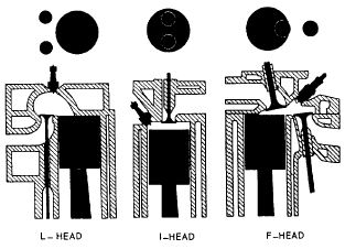
The majority of internal combustion engines also are classified according to the position and arrangement of the intake and exhaust valves. This classification depends on whether the valves are in the cylinder block or in the cylinder head. Various arrangements have been used; the most common are the L-head, I-head, and F-head (fig. 12-8). The letter designation is used because the shape of the combustion chamber resembles the form of the letter identifying it.
L-Head
In the L-head engines, both valves are placed in the block on the same side of the cylinder. The valve-operating mechanism is located directly below the valves, and one camshaft actuates both the intake and exhaust valves.


.
-L-, I-, and F-valve arrangement.


CLASSIFICATION OF ENGINES


CLASSIFICATION OF ENGINES

Engines for automotive and construction equipment may be classified in several ways: type of fuel used, type of cooling employed, or valve and cylinder arrange-ment. They all operate on the internal combustion principle. The application of basic principles of construction to particular needs or systems of manu-facture has caused certain designs to be recognized as conventional.
The most common method of classification is based on the type of fuel used; that is, whether the engine burns gasoline or diesel fuel.

GASOLINE ENGINES VERSUS DIESEL ENGINES


Mechanically and in overall appearance, gasoline and diesel engines resemble one another. However, many parts of the diesel engine are designed to be somewhat heavier and stronger to withstand the higher temperatures and pressures the engine generates. The engines differ also in the fuel used, in the method of introducing it into the cylinders, and in how the air-fuel mixture is ignited. In the gasoline engine, we first mix air and fuel in the carburetor. After this mixture is compressed in the cylinders, it is ignited by an electrical spark from the spark plugs. The source of the energy producing the electrical spark may be a storage battery or a high-tension magneto.
The diesel engine has no carburetor. Air alone enters its cylinders, where it is compressed and reaches a high temperature because of compression. The heat of compression ignites the fuel injected into the cylinder and causes the fuel-air mixture to burn. The diesel engine needs no spark plugs; the very contact of the diesel fuel with the hot air in the cylinder causes ignition. In the gasoline engine the heat compression is not enough to ignite the air-fuel mixture; therefore, spark plugs are necessary.

Engine Cycle


ENGINE CYCLES


Now, with the basic knowledge you have of the parts and the four strokes of the engine, let us see what happens during the actual running of the engine. To produce sustained power, an engine must repeatedly complete one series of the four strokes: intake, compression, power, and exhaust. One completion of this series of strokes is known as a cycle.
Most engines of today operate on four-stroke cycles, although we use the term four-cycle engines to refer to them. The term actually refers to the four strokes of the piston, two up and two down, not the number of cycles completed. For the engine to operate, the piston continually repeats the four-stroke cycle.

TWO-CYCLE ENGINE

In the two-cycle engine, the entire series of strokes (intake, compression, power, and exhaust) takes place in two piston strokes.

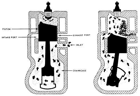
-Events in a two-cycle, internal combustion engine.
is engine is a power stroke. Each time the piston moves down, it is on the power stroke. Intake, compression, power, and exhaust still take place; but they are completed in just two strokes. Figure 12-5 shows that the intake and exhaust ports are cut into the cylinder wall instead of at the top of the combustion chamber as in the four-cycle engine. As the piston moves down on its power stroke, it first uncovers the exhaust port to let burned gases escape and then uncovers the intake port to allow a new fuel-air mixture to enter the combustion chamber. Then on the upward stroke, the piston covers both ports and, at the same time, compresses the new mixture in preparation for ignition and another power stroke.
In the engine shown in figure 12-5, the piston is shaped so that the incoming fuel-air mixture is directed upward, thereby sweeping out ahead of it the burned exhaust gases. Also, there is an inlet into the crankcase through which the fuel-air mixture passes before it enters the cylinder. This inlet is opened as the piston moves upward, but it is sealed as the piston moves downward on the power stroke. The downward moving piston slightly compresses the mixture in the crankcase. That gives the mixture enough pressure to pass rapidly through the intake port as the piston clears this port. This action improves the sweeping-out, or scavenging, effect of the mixture as it enters and clears the burned gases from the cylinder through the exhaust port

4 stroke engine

INTAKE STROKE


The first stroke in the sequence is the intake stroke (fig. 12-4). During this stroke, the piston is moving downward and the intake valve is open. This downward movement of the piston produces a partial vacuum in the cylinder, and air and fuel rush into the cylinder past the open intake valve. This action produces a result similar to that which occurs when you drink through a straw. You produce a partial vacuum in your mouth, and the liquid moves up through the straw to fill the vacuum.

COMPRESSION STROKE

When the piston reaches bottom dead center at the end of the intake stroke (and is therefore at the bottom of the cylinder) the intake valve closes and seals the upper end of the cylinder. As the crankshaft continues to rotate, it pushes the connecting rod up against the piston. The piston then moves upward and compresses the combustible mixture in the cylinder. This action is known as the compression stroke (fig. 12-4). In gasoline engines, the mixture is compressed to about one-eighth of its original volume. (In a diesel engine the mixture may be compressed to as little as one-sixteenth of its original volume.) This compression of the air-fuel mixture increases the pressure within the cylinder.  Compressing the mixture in this way makes it more combustible; not only does the pressure in the cylinder go up, but the temperature of the mixture also increases.

POWER STROKE

As the piston reaches top dead center at the end of the compression stroke (and is therefore at the top of the cylinder), the ignition system produces an electric spark. The spark sets fire to the fuel-air mixture. In burning, the mixture gets very hot and expands in all directions. The pressure rises to about 600 to 700 pounds per square inch. Since the piston is the only part that can move, the force produced by the expanding gases forces the piston down. This force, or thrust, is carried through the connecting rod to the crankpin on the crankshaft. The crankshaft is given a powerful twist. This is known as the power stroke (fig. 12-4). This turning effort, rapidly repeated in the engine and carried through gears and shafts, will turn the wheels of a vehicle and cause it to move along the highway.

EXHAUST STROKE

After the fuel-air mixture has burned, it must be cleared from the cylinder. Therefore, the exhaust valve opens as the power stroke is finished and the piston starts back up on the exhaust stroke (fig. 12-4). The piston forces the burned gases of the cylinder past the open exhaust valve. The four strokes (intake, compression, power, and exhaust) are continuously repeated as the engine runs.


Sunday, October 24, 2010

Car Alarms Work

Introduction to How Car Alarms Work


The first documented case of car theft was in 1896, only a decade after gas-powered cars were first introduced. From that early era to today, cars have been a natural target for thieves: They are valuable, reasonably easy to resell and they have a built-in getaway system. Some studies claim that a car gets broken into every 20 seconds in the United States alone.
In light of this startling statistic, it's not surprising that millions of Americans have invested in expensive alarm systems. Today, it seems like every other car is equipped with sophisticated electronic sensors, blaring sirens and remote-activation systems. These cars are high-security fortresses on wheels!
In this article, we'll look at modern car alarms to find out what they do and how they do it. It's amazing how elaborate modern car alarms are, but it's even more remarkable that car thieves still find a way to get past them.

The Basics
If you want to think about a car alarm in its simplest form, it is nothing but one or more sensors connected to some sort of siren. The very simplest alarm would have a switch on the driver's door, and it would be wired so that if someone opened the door the siren would start wailing. You could implement this car alarm with a switch, a couple of pieces of wire and a siren.
Most modern car alarm systems are much more sophisticated than

Saturday, October 23, 2010

How to Bleed a Diesel 6.2 Fuel System

Bleeding a GM 6.2 diesel fuel system purges air from the fuel lines between the fuel tank and the injection pump. Air sometimes enters the fuel system following replacement of fuel filters or when fuel lines and connections are broken or leaking. GM modified this fuel system several times during the period of manufacture--from 1982 to 1993--so be sure you can identify all of the components in your own engine's fuel system before beginning.

Instructions


Identify Your GM 6.2 Diesel Fuel System Components

  • 1. Check what year your engine was manufactured. You can do this by checking your insurance papers, or look on the post on the driver's side door where you will find a metal printed tag that states the year of manufacture and other information like engine size and type.

  • 2. If your engine was manufactured in 1982 or 1983, it will have a spin-on primary fuel filter mounted on the firewall. The secondary filter is either a spin-on type mounted on the back of the intake manifold or a box-type filter on the intake manifold.

  • 3. If your diesel engine was manufactured in 1984 or later, it has only one fuel filter mounted on the firewall. This box-type filter has fuel inlet and outlet ports, an air bleed valve to allow release of air and retaining clips to hold the filter in place. This filter assembly heats fuel, separates water and dirt from the fuel and has a filter change signal device built in as well.

  • Bleeding 1982 and 1983 GM 6.2 Diesel Engines

  • 1. Fill the primary filter up with clean diesel fuel and screw it into place, giving it three-quarters of a turn after the gasket touches the metal ring. If there are no other leaks or changes in your fuel system, you can start the motor at this point and let it run to purge any last air from the top filter.

  • 2. To bleed the rest of the fuel system, you must now bleed the secondary filter as well. Remove the air filter assembly and locate the secondary filter on the intake manifold.

  • 3. Disconnect the pink wire from the fuel injection pump to prevent the engine from starting when you crank it.

  • 4. Put a rag under the fuel outlet on the secondary filter and crank the engine for 10 seconds or less until fuel flows from the outlet. If no fuel comes out, let the engine sit for 15 seconds and crank it again. When fuel flows out, connect the fuel line to the outlet and tighten it.

  • 5. Connect the pink wire back to the fuel injector, start the engine and let it idle. This will purge any remaining air in the fuel system.

  • 6. Be sure to check all the fuel lines, filters and connections for leaks.
  • Ford Diesel Engine Injection Timing Kit Instructions

    Incorrect or out of phase engine timing can result in mechanical contact between the valve head and the piston crown causing serious damage to the engine. No responsibility can be accepted for any loss or damage arising from the incorrect use of this kit. For 1.6 and 1.8 diesel engines as fitted to Ford Fiesta, Escort, Orion P100, Sierra and Mondeo models, and 2.5DI (direct injection) diesel engines as fitted to Ford Transit models, (February 1985 onwards). This comprehensive kit enables correct engine timing alignment to be maintained when the engine timing belt either needs to be replaced, or removed and re-fitted as part of a service procedure.

    Suitable for use on the following vehicles:
    1.6 Diesel Engine - 4 Cylinder 1608cc OHC

    1. Follow workshop manual instructions to remove the camshaft cover and the timing belt cover.

    2. Turn the engine (in the normal direction of rotation) until the timing mark on the injection pump sprocket lines up with the cast lug on the timing cover.

    3. Remove the threaded plug from the cylinder block (between the alternator and the injection pump) and screw in the T.D.C. Setting Pin. Slowly turn the crankshaft clockwise, until contact is made with the setting pin, to put No.1 cylinder at Top Dead Centre.

    4. Insert the Locking Plate into the groove in the tail of the camshaft with the larger semi-circle facing upwards. If required, pack each side of the plate with equal thickness feeler gauges to obtain a tight fit and the correct camshaft alignment.

    5. Slacken the camshaft sprocket bolt (DO NOT REMOVE). If the timing belt is to be re-used, mark the direction of rotation with chalk to ensure correct refitting. Slacken the timing belt tensioner and remove the timing belt.

    6. Check that the crankshaft has been turned clockwise against the setting pin and that the Locking Plate is correctly positioned (as in 4 above). Fit the timing belt (in the correct direction of rotation). Fasten the *Torx belt tensioner bolt finger tight.

    7. Ensure that the camshaft sprocket can turn on its taper, and turn the tensioner anticlockwise to obtain the correct tension (REFER TO WORKSHOP MANUAL). Tighten the *Torx belt tensioner retaining bolt.

    8. Tighten the camshaft sprocket bolt to the specified torque, and remove the Locking Plate and T.D.C.
     Setting Pin. Turn engine over twice by hand to complete a full cycle. Re-gain T.D.C. Position and re-check alignment by inserting the locking plate with the T.D.C. setting pin in place (see above). If necessary repeat steps 6 & 7 before proceeding. Remove the locking plate and T.D.C. pin before turning the engine over twice by hand to complete a full cycle to ensure that there is no obstruction.

    9. Replace the threaded plug in the cylinder block and follow workshop manual instructions to refit the camshaft cover and the timing belt covers, etc.

    1.8 Diesel Engine - 4 cylinder 1753cc OHC

    1. Follow workshop manual procedures to remove the timing belt covers. Remove the threaded plug for the crankshaft timing pin from the cylinder block and turn the engine until the slot in the injection pump pulley is at about 11 o’clock.

    2. Screw the T.D.C. Setting Pin into the cylinder block and turn the crankshaft until it rests against the setting pin at T.D.C. The drilling in the (CAV) injection pump flange, or the recess (Bosch), should be aligned with the drilling in the pump housing. If the timing belt is to be re-used, mark the direction of rotation with chalk to ensure correct re-fitting. Release the belt tensioner to remove the camshaft toothed belt. DO NOT REMOVE THE INJECTION PUMP TOOTHED BELT UNLESS NECESSARY, AS THE SPECIFIED TENSIONING PROCEDURE ONLY APPLIES TO NEW BELTS.

    3. Bosch pump - use pin ‘B’ to time the injection pump sprocket and pin ‘D’ to time the camshaft sprocket. CAV pump - use pin ‘E’ to time the injection pump sprocket and pin ‘D’ to time the camshaft sprocket.

    4. Ensuring that the crankshaft is still in contact with the T.D.C. Setting Pin, fit the new injection pump toothed belt and/or the camshaft toothed belt. Ensure direction arrows point the correct way. REFER TO WORKSHOP MANUAL FOR DETAILED BELT FITTING AND TENSIONING PROCEDURES.

    5. Remove all pins, and turn engine over twice by hand to complete a full cycle. Re-gain T.D.C. position and re-check alignment by inserting the appropriate pins. If the pins do not all fit correctly repeat step 4 before proceeding. Remove all pins and turn engine over twice by hand to complete a full cycle to ensure that there is no obstruction.

    6. Replace threaded plug in the cylinder block and follow workshop manual procedures to re-fit timing belt covers, etc.

    2.5DI Diesel Engine - 4 Cylinder 2496cc OHV Direct Injection.

    1. Follow workshop manual procedures to remove the timing belt covers. Remove the blanking plug for the crankshaft timing pin from the the cylinder block. Turn the engine in the normal direction of rotation until the Setting Pin ‘A’ can be inserted into the flywheel. Check that pin ‘C’ and pin ‘D’ can be inserted in the camshaft and injection pump sprockets respectively.

    2. To remove the timing belt, slacken the tensioner bolts and lever the tensioner away from the belt. If the timing belt is to be re-used, mark the direction of rotation with chalk to ensure correct re-fitting.

    3. Ensure that the three timing pins are correctly located and that the belt tensioner is held back against the spring with the clamping bolt. REFER TO WORKSHOP MANUAL FOR DETAILED BELT FITTING AND TENSIONING PROCEDURES.

    4. Remove all pins, and turn engine over twice by hand to complete a full cycle. Re-gain timing position and re-check alignment by inserting the appropriate pins. If the pins do not all fit correctly repeat step 3 before proceeding. Remove all pins and turn engine over twice by hand to complete a full cycle to ensure that there is no obstruction/

    5. Replace blanking plug in the cylinder block and follow workshop manual procedures to re-fit belt covers, etc.

    Why Bleed the Air Out of a Propane Tank

    About Propane Tanks

  • Propane tanks are reinforced storage vessels designed to hold liquid propane at extremely high pressure. They can be small enough to carry around or large enough to hold thousands of gallons. Propane is highly flammable, and the most common uses for propane tanks are to provide fuel for barbecue grills, home and RV heating systems and industrial equipment.

  • Relief Valves and Propane Tank Pressure

  • Because propane tanks store liquid propane at such high pressure, they are fitted with safety relief valves. When the pressure inside a propane tank rises to a level that may be unsafe, air will automatically bleed out through this valve. In most cases, pressure rises inside propane tanks when they're left outdoors on hot days, which heats up the air trapped inside the tanks. The propane, which is heavier than air, sinks to the bottom of the tank, while the air fills the top of the tank near where the safety relief valve is installed. Without a safety valve, the pressure of the hot air trapped inside a tank can reach dangerous levels under high-temperature conditions. If these pressure levels build to a breaking point, the tank could rupture, causing a violent explosion and producing a great risk of fire.

  • How Propane Relief Valves Work

  • The stem of a propane tank safety-relief valve is wrapped in a heavy metal spring. The spring is calibrated so that its pressure will keep the relief valve closed whenever pressure conditions inside the tank are normal. If and when the pressure rises to a point where it equals the tension pressure on the spring, it allows the valve to open slightly, which automatically bleeds air out of the tank and relieves the pressure. An audible hissing noise may be heard coming from a tank that is releasing pressure in this way. The valve will only open completely if the pressure inside the tank surges significantly. When the valve opens all the way, it often makes a loud popping sound, and the pressurized air is released very quickly. Although this is by design as a safety precaution, the somewhat violent action of a safety valve that springs open suddenly can damage the valve. Propane tanks with relief valves that have fully opened should be inspected immediately for damage and possible service by a trained technician.


  • Changing Automatic Transmission Fluid

    Voyager transmission fluid change and band adjustment

    Lane MacFarlane wrote:

    I changed the fluid and filter, and adjusted the bands on our 85 Voyager (2.6L, A470 3-speed, 118,000 miles). The fluid was no longer bright red, but tired dark reddish brown. No burned smell, no flakes, no particles, so that's good! I suspect (as the second owner) this is the first transmission fluid change it's ever had.
    The purpose in posting this note is to encourage anyone with an A470/A413 (3 speed 2.6L or 2.2L) to change the fluid and filter if they think it's time. No need to pay someone else $35 to do a half-hearted job! It's a simple, uncrowded, easy to maintain design, and if you can do a valve cover gasket on an overhead-cam engine, you can do this (in my opinion).
    Get that new ATF 3+ (Chrysler MS-7176, US$3.50 at my local CPJE emporium, get four or five quarts), get a real MoPar filter for US $7.95 and rubber gasket for US $1.70, and do it! [Editor’s note: in the years since this was posted, in the 1990s, Mopar moved to ATF+4, which is acceptable in the older transmissions.]
    You'll need a decent torque wrench capable of reading down to 40 in-lbs for the band adjustment and up to 175 in-lb for the pan bolts, and a factory service manual or equivalent for the torque and backoff turns figures, but that's something most of us have anyway. Also, you'll need a Torx (TM) -type screwdriver (like the one used on the headlight housings) for the filter screws. The fastener sizes quoted are for the 1985 A470, other years may be different.
    Watch out when you pull the pan, don't damage the sealing surface prying the pan off (do it gently and you'll be OK, it'll sort of jump loose all the sudden). Getting a premium gasket and sealing agent (if called for) is worthwhile.

    Adjusting the low/reverse band is easy, you'll have to remove the parking sprag pushrod (e-clip) to gain access, then loosen the locknut with a 13mm open or box end or socket. The adjusting nut is a 6mm hex (I think that's what I used at least), torque it down carefully to the FSM spec then back it off the number of turns specified in the FSM. I painted two stripes 180 degrees apart on my 1/4" to 3/8" adapter to see when I'd gone 1/2 and one full turn.
    Hold the adjusting hex when you tighten the locknut so it doesn't move. Don't forget to put the parking sprag pushrod and e-clip back in! Adjusting the kickdown band is also pretty easy, it's on top of the case under the throttle cable. It uses an 18mm locknut and an 8mm hex adjuster. Use an 18mm box end to loosen and tighten the locknut.
    Clean the pan and case gasket surfaces thoroughly and gently so as not to gouge the aluminum of the case...a wire brush worked OK on the pan itself. Don't forget to put in the new filter and filter gasket! Clean the old residue out of the pan, and clean the magnetic residue off the ring magnet in the pan. Might as well do the differential cover gasket, too, since removing it drains the fluid out. I had a leak in the differential cover gasket anyway, so I had to do it. Watch out for the constant dripping from the case, try to keep the mating surfaces clean when you put the pan and cover back on, it'll help it seal better. If using RTV, use a 1/8" bead of RTV on the pan and cover, don't overdo it, ring the bolt holes, go slowly.
    Watch out for the differential cover not being aligned with the case holes, just align the cover carefully and you'll be OK. Torque the pan and cover immediately upon putting it in, to keep the dripping fluid from messing up the seal (especially on the differential cover). Above all else, keep the insides of the transmission clean, no lint.
    Put in the recommended quantity of fluid (4 qts US for the 1985 A470), and test it out! You'll be rewarded with a job as good as your capabilities allow, for much less money, and with high-quality parts and fluid. You'll also get a good look inside the tranny, to see what's up in there (any particles of old friction material in there, for example).

    How to Change Power Steering Fluid

    It's a good idea to replace the power-steering fluid every time you change your engine's coolant.
    It's a good idea to replace the power-steering fluid every time you change your engine's coolant.
    steering wheel and dash of british sports car image by Bo Widerberg from Fotolia.com
    Power-steering fluid, like any other fluid under your hood, breaks down over time and needs to be replaced. As a rule of thumb, it is a good idea to replace the power-steering fluid every time you change your engine's coolant. While most manufacturers don't specify how often power-steering fluid should be changed, it is a good idea to check the fluid every so often and replace it when you note a color change (darkening from a pinkish color).
    Difficulty: Moderate

    Procedures for Changing the Rear Differential Fluid on a Chevy 2000 Silverado

    Changing the differential fluid in your light truck will extend the life of its drivetrain.
    Changing the differential fluid in your light truck will extend the life of its drivetrain.
    red truck single cab side view image by patrimonio designs from Fotolia.com
    Changing the rear differential fluid in a 2000 Chevrolet Siverado can extend the life of the truck's drivetrain. The 2000 Silverado came with optional two-wheel drive and four-wheel drive systems. The two-wheel drive version has only one differential in the rear, while the four-wheel drive model has two differentials and a transfer case, all of which require fluid changes. Changing the rear differential fluid should take approximately two hours, if you have never done this type of work before. All of the tools and materials for this project are available at auto parts stores.
    Difficulty: Moderate

    Instructions

    1. Raise the rear of the vehicle slightly, so that you can access the rear differential housing. Set wheel chocks in front of the front tires. Set jack stands underneath the axle housing on either side of the truck.

    2. Set a drain pan beneath the differential housing. Remove the differential plug, using the head of a 3/8-inch drive ratchet to turn the drain plug. Turn the drain plug counterclockwise to remove it.

    3. Allow the differential to drain for approximately 10 minutes. This will ensure that you have removed as 
      much fluid as possible. Use a hand-held siphon pump to pump the remaining fluid from the differential into a drain pan. The siphon pump will also remove the majority of floating metal grindings from inside the differential housing.

    4. Reinstall the differential drain plug. Tighten the plug to between 35 and 50 foot-pounds of torque. Do not run the drain plug all the way into the housing, or you will break the seal or damage the differential's gears.
    5. Remove the fill plug from the differential in the same manner that you removed the drain plug. Place the inlet hose of the siphon pump into a bottle of 80w-90 or 85w-140 gear oil. Place the outlet hose of the siphon pump into the fill hole of the differential.

    6. Pump differential fluid into the differential until you have a small amount of drip or seepage coming from the fill hole.
    7. Remove the siphon pump. Insert the fill plug into the differential. Tighten the plug to between 35 and 50 foot-pounds of torque. Do not over-tighten the plug or run it through the differential.

    8. Remove the drain pan from beneath the vehicle. Discard the used gear oil at a local auto parts store or oil change center--both of these places offer free oil disposal.

    9. Lower the vehicle to the ground.

    How to Change the Ford 9 Differential Fluid

    Ford's 9-inch differential is known for its durability.
    Ford's 9-inch differential is known for its durability.
    wrench image by AGphotographer from Fotolia.com
    Along with the 10-bolt differential produced by General Motors, Ford's 9-inch differential is among the most popular differentials with automotive enthusiasts. Ford first produced the 9-inch differential in 1957, but eventually phased out production by the end of the 1980s. The differential consists of two gears, which rotate along with the drive shaft. The differential makes use of a heavy fluid, which keeps the gears lubricated and cool. The fluid can be quickly changed with the assistance of a fluid pump.
    Difficulty: Moderately Easy

    Don't Forget the Gear Oil

    Maintaining a vehicle requires the use of many lubricants, each specifically designed to perform a certain task or set of tasks. The most common lubricant requiring routine attention from motorists is engine oil. Gear oil, on the other hand, is often-times overlooked when it comes to scheduled maintenance.

    Gear Oil Basics

    High quality gear oils must lubricate, cool and protect geared systems. They must also carry damaging wear debris away from contact zones and muffle the sound of gear operation. Commonly used in differential gears and standard transmission applications in commercial and passenger vehicles, as well as a variety of industrial machinery, gear oils must offer extreme temperature and pressure protection in order to prevent wear, pitting, spalling, scoring, scuffing and other types of damage that result in equipment failure and downtime. Protection against oxidation, thermal degradation, rust, copper corrosion and foaming is also important.

    How to Check Clutch Fluid Level

    While there's no such thing as special "clutch fluid," hydraulic clutches use brake fluid instead. It's a good idea to check the fluid level in the clutch reservoir regularly.

    Instructions

    1. Turn the engine off before opening the hood.
    2. 2
      Find the clutch fluid reservoir. It's usually close to the back of the engine, near the brake fluid reservoir.
    3. 3
      Take off the cap.
    4. 4
      Check the fluid level. If it is not filled to the top, you will need to add brake fluid. (See "How to Add Brake Fluid to the Clutch Master Cylinder" under Related eHows.)
    5. 5
      Replace the cap tightly.


    New 2011 Ford Explorer will be available with 4-cylinder engine

    New 2011 Ford Explorer will be available with 4-cylinder engine


    The 2011 Ford Explorer features front- all four-wheel drive with unibody construction and three rows of seats. The engine choices include standard 3.5-liter V6 with Twin independent variable camshaft timing (Ti-VCT) and available advanced 2.0-liter 237-hp EcoBoost turbocharged and intercooled 4-cylinder engine with direct injection. Either engine will be paired with 6-speed automatic transmission.
    Among other innovations, the 2011 Explorer will feature electric power steering, variable-displacement air-conditioning compressor and the world's first second-row inflatable rear seat belts.
    Available Explorer safety features include Adaptive cruise control and collision warning with brake support and BLIS® (Blind Spot Information System) with cross-traffic alert.
    Explorer V6 models can be equipped to tow up to 5,000 pounds.
    The 2011 Explorer will be assembled at Ford's Chicago manufacturing facility. Production begins late this year, and Explorer will be available in dealerships this winter. It will be equipped by 6-speed automatic transmission.

    Breaking: Automotive Media drive the new 2011 BMW X3

    Very unexpected and unusual of BMW to allow automotive journalists to test drive a car prior to its unveiling, but selected journalists in Europe had the opportunity to spend some time behind the wheel of a camouflaged 2011 BMW X3.
    And here are some new things that we have learned. The new F25 BMW X3 will come only in an all-wheel-drive flavor. Initially, the 2011 X3 will be offered with an 184 horsepower diesel engine and the 3.0 liter turbocharged petrol engine with 306 horsepower.
    The new X3 has a striking resemblance to its big brother, the X5 SAV, and the similarities are even more noticeable inside the cabin. Unfortunately, the interior design was covered with the usual camouflage, and no dashboard photos were allowed.
    2011-bmw-x3-test-drive-1
    With the new F25 platform, the 2011 BMW X3 uses many components from both the 3 Series and 5 Series. The compact SAV grew in size 8 centimeters long, 3 cm wide and 1.2 cm in height. The wheelbase was also extended by 9 cm.

    How to check a used car prior purchase

    How to check used car history records by the VIN number

    I recommend to check a used car's history records as a first step before buying a car.
    The used car history report can't give you a 100-percent guarantee that the car is perfect, but when you about to spend thousands of dollars on a used car, it is worth to pay for a history report that could give you some information about the car's past. Here are few examples of the information you may find in a used car history report:
    The car was totaled in an accident/salvaged
    Flood damage
    Odometer rollbacks
    Lemon histories
    Junked Titles
    State emissions inspection results
    Lien activity, and/or
    Vehicle use (taxi, rental, lease, etc.)
    If available, service and repair history 

    Look at the picture I made at a collision repair shop yard. Why do you think they keep that rear piece of the car? Because when they find the same vehicle with rear-end damage, they will just weld two pieces together into one car, paint it nicely and sell it through the auction somewhere in a different state or province. Soon it may appear in a used car dealer lot as "Immaculate condition with low mileage" vehicle. The car may look clean and shiny, but if you check the car history report, you may find that the vehicle was salvaged.

    Another example: I received a message from the person who bought privately a "low mileage" car. He even had it inspected by a dealer and had been told that the car is OK. Few days later, he checked the used car history report and found out that previous reported mileage was a lot higher - very unfortunate situation.
    By the way, when you bring a used car to a mechanic or a dealer for an inspection, have a look at items covered in the inspection checklist - usually it does not include things like previous accident check or odometer fraud check.

    For these reasons, when buying a used car, it is worth to check the used car history as a first step and then have a car inspected by a mechanic of your choice. 


    HINTS AND TIPS WHEN BUYING A SECONDHAND / USED CAR

    What to look out for when buying used cars

    This is always a mine field and nothing guarantees success but there are a few things to look out for before parting with your hard earned cash.

    Obviously different countries have different rules but I am sure a lot of the following would apply wherever you are located.


    PRE-SHOPPING ADVICE

    The depreciation of used cars is much less than new cars and, therefore, they are a more cost effective purchase.

    Get your finance in place before choosing your car, this saves time as you know exactly which vehicles you can or cannot afford.

    Be aware of the current "going rate" of vehicles before purchasing by checking guides available from most newsagents that list the value of most used cars.

    Consider all different outlets such as trade-ins at new car dealerships, private sales etc., not just secondhand car dealers. In the U.K., however, the purchaser has more rights and safeguards when purchasing through trade rather than a private sale.

    Cars less than three years old which have been driven 10,000 - 15,000 annually are probably the best buys. An average annual mileage is about 10,000, so for a 3 year old car mileage between 25,000 and 35,000 would be reasonable. Anything over this could have been used for business and driven hard.

    Small and medium saloons and hatchbacks are easier to maintain and repair than convertibles or luxury cars.

    Read external buying a car reviews on ciao.


    GENERAL ADVICE WHEN INSPECTING VEHICLES
    Check the engine plate on the car corresponds with that given on the registration documents and that it has not been tampered with or changed.

    Never buy a car without test driving is yourself.


    First make sure you are insured to drive it then, if possible, take it on a drive that covers a mixture of conditions i.e. fast motorway driving, slow urban driving, twisting roads and don't forget to check reverse.

    BODYWORK

    Always inspect the bodywork in good light.

    Look for corrosion or rust. Rust is probably the most damaging thing of all on cars over five years old.
    Surface blisters can be relatively harmless and easily treated but corrosion coming from the inside of the body panels is more serious.

    Look for rust at the top and rear of the front wings, along the side sills, below front and rear bumpers and the bottoms of the doors.

    Sometimes a rust blemish on the paintwork can indicate more serious corrosion underneath. Press the panel gently with your thumb. If there is a cracking noise it indicates advanced corrosion.

    It is usually not worth repairing rust that has perforated the bottom of doors, the bodywork around the front and rear screen rubbers, on trailing edges of bootlids or tailgates and leading edges of bonnets and on rear wing panels. These can only be repaired expensively by specialists and subsequent painting is costly.

    Walk around the car and look along the doors and wings from each of the four corners. Any crash repairs will show up if they have not been well done. You will see ripples or a change in the texture of the paint if there is a lot of body filler underneath. Take a small magnet with you, it will be attracted to metal but not to plastic body filler. Look also for variations in the paint colour.

    Water stains in the boot, around windows, on carpets and around the sunroof opening may indicate leaks.

    STRUCTURAL BODYWORK

    Look for rust perforation on inner wings, the bulkhead and any cross members and chassis members visible under the bonnet. If you see any, reject the car.

    Beneath the car check side sills, chassis legs, cross members and subframes. Tap suspicious areas with a lightweight hammer, or push hard with your hand to detect the 'give' of weakened metal. Be wary of freshly applied underseal - could be hiding weakened metal.

    Check the floorpan for corrosion.

    Look at brake pipes, if they are crusted or pitted with rust, these could be dangerous.

    Check suspension and steering mounting points for serious corrosion, especially under the bonnet.


    COLLISION DAMAGE

    A car that has been in a collision can be dangerous, especially if its suspension and/or steering have been damaged.
    Examine under the bonnet for damage, creasing or replaced inner wings (unsightly welds are a give-away). Also inspect the engine bay forward panels and forward chassis legs for repairs or creases.

    When test driving the car the steering should be consistent with no tendency to pull either left or right.

    Look under the carpet between the front and back doors for signs of welding or repair in case two halves of different cars have been welded together (cut and shut), which is extremely dangerous.

    Buy your used cars from recognised dealers using Teletextcars.co.uk
    Related Posts Plugin for WordPress, Blogger...